How you write your code matters. The wrong constructs can slow execution, make your code less understandable, hide bugs, and complicate maintenance. These are the types of costly problems that you might avoid with regular, automated refactoring.
Code refactoring entails restructuring code in a way that does not change its functionality–it not only makes your code cleaner, more readable, healthier, and easier to maintain, but also helps detect issues early, when they cost minutes of engineering time instead of millions of dollars..
In this article we’ll provide a detailed view of how design, verification, and IP engineers working with Verilog and SystemVerilog can leverage refactoring.
Why Refactor Code
There are several reasons why refactoring is valuable and well worth the effort:
Improves performance while running on one or more processors. Complex languages offer multiple ways to do the same task, and refactoring helps you pick the fastest, leanest approach—boosting execution speed and cutting memory use.
Enhances code readability. Clear structures and descriptive names reduce hidden bugs, boost reuse, and make it far easier to adopt or hand off code without wrestling with convoluted logic.
Simplifies code maintenance. By extracting repeated segments into functions or tasks, refactoring lets you update logic in one place rather than risk multiple, error-prone edits.
These benefits apply to any programming language, as well as the Verilog and SystemVerilog hardware languages used in chip design and verification. Refactoring can dramatically improve RTL and testbench simulation throughput and memory use, and by choosing synthesis-friendly constructs it’s easier to hit your PPA (power, performance, area) targets.
Refactoring RTL Designs
Both Verilog and SystemVerilog have subsets ideal for describing chip hardware and compatible with logic synthesis tools. That means you can write at the RTL level and let EDA tools turn the code into an actual chip layout.
Although RTL design code is often less complex than most verification code, it’s still quite sophisticated–and refactoring can play a key role improving its performance, readability, maintainability, and reusability.
Below are a few cases where code refactoring can help with your RTL designs:
Style and Formatting Improvements
Perhaps the simplest form of refactoring is formatting the white space around the code without altering any of the code itself. The legacy term “pretty printing” understates the benefits of logical and consistent formatting. Code becomes easier to write, understand, modify, and debug. Examples of white space refactoring for RTL code include:
- Trimming whitespace from the end of lines
- Compressing whitespace to as few tabs and spaces as possible
- Adding whitespace before or after specified language constructs
- Wrapping lines that are too long
- Placing ports, declarations, arguments, and parameters one per line or multiple on a single line
- Indenting and vertical alignment of code, as shown in the table below.
| Refactor | Example |
|---|---|
| Alignment of assignments | |
| Alignment of name port connections | |
| Alignment of module signal declarations | |
Examples of indentation and vertical alignment refactoring.
Enforcing a common style makes it much easier for engineers to understand code they didn’t write, or even their own code after an extended period, and reuse it. Many projects have code formatting rules for just this reason. Naming guidelines for design elements (modules, functions, ports, arguments, macros, variables, etc.) are also quite common.
Refactoring Repeated Expressions
Another example of design refactoring is replacing an expression with a variable. You can define the new variable, set it equal to the expression, and replace the original expression with the new variable. This makes your code more compact and easier to understand.
Example: The before-and-after snippet below shows how moving the long address-and-enable test into one wire (addr_enable_ok) cuts duplication, reads better, and keeps future edits in one spot.
// Before refactoring
assign first_in_fifo = fifo_is_empty && (addr == BASE_ADDR) && (enable && !error);

always_ff @(posedge clk) begin
  if ((addr == BASE_ADDR) && (enable && !error)) begin
    // process data
  end
end

// After refactoring
assign addr_enable_ok = (addr == BASE_ADDR) && enable && !error;

assign first_in_fifo = fifo_is_empty && addr_enable_ok;

always_ff @(posedge clk) begin
  if (addr_enable_ok) begin
    // process data
  end
end
The new variable can be referenced anywhere in the code, saving you typing and possible errors. If you later change the functionality, you only need to edit the variable definition. This is much faster and less error-prone than manually changing multiple instances of the same repeated code.
Improving Readability with Logic Restructuring
In some cases, deeply nested if statements make code hard to follow, so you can refactor the control logic into case statements, or vice versa, for better readability and to align with RTL synthesis guidelines.
Example: The snippet below illustrates how replacing the deep if/else chain with a short case statement keeps the logic identical but is far easier to read, while generating identical synthesis results.
// Before refactoring: deeply nested if/else
always_comb begin
  if (state == IDLE) begin
    next_state = START;
  end else if (state == START) begin
    if (valid) begin
      next_state = RUN;
    end else begin
      next_state = IDLE;
    end
  end else if (state == RUN) begin
    if (error) begin
      next_state = ERROR;
    end else if (done) begin
      next_state = IDLE;
    end else begin
      next_state = RUN;
    end
  end else begin
    next_state = IDLE;
  end
end

// After refactoring: clearer state transition table.
// Note that Synthesis QoR is unchanged – the case statement
// maps to the same combinational decode logic and
// timing/area/power as the nested if/else chain.
always_comb begin
  case (state)
    IDLE:   next_state = START;
    START:  next_state = valid ? RUN  : IDLE;
    RUN:    next_state = error ? ERROR : (done ? IDLE : RUN);
    default: next_state = IDLE;
  endcase
end
Modularizing Design for Reuse and Clarity
As a project progresses, module boundaries might evolve or parts of modules might be earmarked for reuse. You can split a complex block into multiple smaller blocks - for example, an Ethernet or PCI Express (PCIe) interface into separate transmitter and receiver modules. Or you could merge related small modules into one cohesive unit for easier understanding and more convenient reuse of the overall functionality–a key objective of structural refactoring.
Example: Here’s the modularization refactor in practice, where I split one Ethernet block into two: eth_tx for transmit and eth_rx for receive. Each can be reused alone, and a thin wrapper ties them back together when you need the full interface.
// Before refactoring: monolithic Ethernet block
module eth_top (
    input  logic       clk,
    input  logic       rst_n,
    input  logic [7:0] mac_data_in,
    output logic [7:0] mac_data_out,
    input  logic       phy_rx,
    output logic       phy_tx
);
  // TX and RX logic intermingled here...
endmodule

// After refactoring: separate TX and RX into reusable modules
module eth_tx (
    input  logic       clk,
    input  logic       rst_n,
    input  logic [7:0] mac_data_in,
    output logic       phy_tx
);
  // Transmit logic...
endmodule

module eth_rx (
    input  logic       clk,
    input  logic       rst_n,
    input  logic       phy_rx,
    output logic [7:0] mac_data_out
);
  // Receive logic...
endmodule

module eth_top (
    input  logic       clk,
    input  logic       rst_n,
    input  logic [7:0] mac_data_in,
    output logic [7:0] mac_data_out,
    input  logic       phy_rx,
    output logic       phy_tx
);
  eth_tx u_tx (
    .clk          (clk),
    .rst_n        (rst_n),
    .mac_data_in  (mac_data_in),
    .phy_tx       (phy_tx)
  );

  eth_rx u_rx (
    .clk           (clk),
    .rst_n         (rst_n),
    .phy_rx        (phy_rx),
    .mac_data_out  (mac_data_out)
  );
endmodule
Refactoring Verification Code
Verifying the functionality of every RTL design is an essential step in chip development.
Making mask sets and fabricating prototype silicon for modern deep submicron technology nodes cost millions of dollars. Every chip turn carries most or all of these same costs. In addition, debugging hardware errors in the bringup lab is highly inefficient. Thus, the goal is to eliminate as many bugs as possible before the initial tapeout and to minimize chip turns. That means you need an extremely sophisticated verification environment (testbench), directed-random testing, and rigorous coverage metrics.
Virtually all chip projects use SystemVerilog and the Universal Verification Methodology (UVM) for structuring tests and testbenches. UVM supports verification reuse across projects and defines some testbench components that can be reused from block-level verification to full-chip verification.
Style and Formatting Improvements
All the design refactoring operations, including reformatting and renaming, apply equally well to verification code. These operations extend to support constructs such as classes that aren’t accepted by most RTL synthesis tools. For example, indenting and vertical alignment refactoring also applies to class parameters and variable declarations.
Consistent formatting makes verification environments easier to understand and maintain—especially when shared across teams or reused across projects.
Example: Below you can see how proper indentation clearly reflects the if guarded statement.
| Before | After |
|---|---|
|
|
Refactoring Classes and Sequences
Splitting and merging design modules translates into the verification domain as well: similar classes can be refactored into a common base class with multiple extensions, and similar sequences might be consolidated into a single parameterized sequence.
This improves reusability and helps enforce consistent behavior across different testbench components.
Example: The SystemVerilog example below folds separate read and write sequences into one generic io_seq class, then adds tiny aliases for each use.
typedef enum {READ, WRITE} op_e;

// Before refactoring
class write_seq extends uvm_sequence#(pkt);
  task body();
    pkt req;
    start_item(req);
    req.op = WRITE;
    finish_item(req);
  endtask
endclass

class read_seq extends uvm_sequence#(pkt);
  task body();
    pkt req;
    start_item(req);
    req.op = READ;
    finish_item(req);
  endtask
endclass

// After refactoring: parameterized class
class io_seq#(parameter op_e OP = WRITE) extends uvm_sequence#(pkt);
  task body();
    pkt req;
    start_item(req);
    req.op = OP;
    finish_item(req);
  endtask
endclass

// Specialized aliases
class write_seq extends io_seq#(.OP(WRITE)); endclass
class read_seq  extends io_seq#(.OP(READ));  endclass
Refactoring Interfaces and Connections
Although SystemVerilog interfaces are rarely used in synthesized design code, they are common in verification testbenches. Interfaces bundle signals—and sometimes variables, functions, and tasks—into a single connection element. They reduce the complexity of port connections and may eliminate duplicated code on both ends of the interface. Defining an interface, or converting it back into signals, is another form of refactoring.
Verilog has limited capabilities for verification, but SystemVerilog has a rich mix of constructs so that the same task can be accomplished in multiple ways. Part of refactoring includes choosing the form that best facilitates reuse and reduces potential errors.
Example: The snippet swaps four individual design signals for one dut_if interface bundle.
// Before: explicit signals and port connections
module tb;
  logic clk, rst_n, req, ack;
  dut u_dut (
    .clk   (clk),
    .rst_n (rst_n),
    .req   (req),
    .ack   (ack)
  );
endmodule

// After: bundled signals in an interface and single-port connection
interface dut_if(
  input  logic clk,
  input  logic rst_n,
  output logic req,
  input  logic ack
);
endinterface

module tb;
  logic clk, rst_n;
  dut_if bus_if(clk, rst_n, req, ack);
  dut u_dut(bus_if);
endmodule
Replacing Code Blocks with Functions or Tasks
Besides replacing expressions with new variables, you might convert a repeated section of code into a function or task. This refactoring can also help improve readability by splitting large functions into smaller ones.
Example: The next snippet shows how repeated reset code is pulled into a single reset_sequence task, so it lives in only one place.
// Before refactoring: repeated high impedance driving

task reset_signals();
  forever begin
    @(posedge vif.sig_reset);
    vif.sig_request <= 0;
    vif.rw           <= 1'h0;
    vif.sig_addr     <= 16'hz;
    vif.sig_size     <= 2'bz;
    vif.sig_read     <= 1'bz;
    vif.sig_write    <= 1'bz;
  end
endtask

task drive_address_phase (ubus_transfer trans);
  vif.sig_addr  <= trans.addr;
  drive_size(trans.size);
  drive_read_write(trans.read_write);
  @(posedge vif.sig_clock);
  vif.sig_addr  <= 16'bz;
  vif.sig_size  <= 2'bz;
  vif.sig_read  <= 1'bz;
  vif.sig_write <= 1'bz;
endtask

// After refactoring: extracted task

task reset_addr_phase();
  vif.sig_addr  <= 16'hz;
  vif.sig_size  <= 2'bz;
  vif.sig_read  <= 1'bz;
  vif.sig_write <= 1'bz;
endtask

task reset_signals();
  forever begin
    @(posedge vif.sig_reset);
    vif.sig_request <= 0;
    vif.rw          <= 1'h0;
    reset_addr_phase();
  end
endtask

task drive_address_phase (ubus_transfer trans);
  vif.sig_addr  <= trans.addr;
  drive_size(trans.size);
  drive_read_write(trans.read_write);
  @(posedge vif.sig_clock);
  reset_addr_phase();
endtask
Migrating Legacy Environments to UVM
Refactoring also helps migrate legacy verification code to modern UVM-compliant testbenches. The predecessor Open Verification Methodology (OVM) looks rather like UVM, with many similar naming conventions, as you can see in the table below. You can define a set of refactoring rules to do most of the conversion from UVM to OVM, also in the table below. A similar approach works for converting legacy ad hoc testbenches and tests to structured UVM code.
Since you’re not changing the underlying functionality, refactoring prevents you from inadvertently altering the original verification intent.
OVM to UVM Mapping Table
| OVM Macro / Class | UVM Macro / Class |
|---|---|
`ovm_component_utils(MyAgent) |
`uvm_component_utils(MyAgent) |
`ovm_object_utils(MyTransaction) |
`uvm_object_utils(MyTransaction) |
`ovm_info("id", OVM_HIGH, msg) |
`uvm_info("id", UVM_HIGH, msg) |
class my_agent extends ovm_agent |
class my_agent extends uvm_agent |
`include "ovm_macros.svh" |
`include "uvm_macros.svh" |
`ovm_error(ID, MSG) |
`uvm_error(ID, MSG) |
`ovm_warning(ID, MSG) |
`uvm_warning(ID, MSG) |
`ovm_fatal(ID, MSG) |
`uvm_fatal(ID, MSG) |
`ovm_info(ID, MSG, SEV) |
`uvm_info(ID, MSG, SEV) |
Example: The following example shows how converting an OVM agent to UVM just changes the macros and class names, while behavior stays the same.
// Before (OVM)
`include "ovm_macros.svh"

class my_agent extends ovm_agent;
  `ovm_component_utils(my_agent)

  // Example of OVM report macros
  function void build_phase(ovm_phase phase);
    super.build_phase(phase);
    `ovm_info  ("AGT", "Starting build-phase", OVM_LOW)
    if (!cfg.exists())
      `ovm_error("AGT", "Configuration object missing")
  endfunction
endclass


// After (UVM)
`include "uvm_macros.svh"

class my_agent extends uvm_agent;
  `uvm_component_utils(my_agent)

  // Same intent, now in UVM dialect
  function void build_phase(uvm_phase phase);
    super.build_phase(phase);
    `uvm_info  ("AGT", "Starting build-phase", UVM_LOW)
    if (!cfg.exists())
      `uvm_error("AGT", "Configuration object missing")
  endfunction
endclass
Refactoring for IP and Reuse
If you develop design or verification IP, refactoring can help you create code that is more portable, more reusable, and easier to understand. The same goes for chip developers who are not official IP providers but whose code might be reused by others on this project or future ones.
Generalizing and Parameterizing Designs
Coding for reuse is almost always a good idea. Reuse inherently demands clearer, cleaner, and more generalized code structures, and refactoring can help a great deal.
For example, you can convert a design developed for one specific use into a parameterized IP block to enable a wider range of reuse scenarios–like varying data widths in arithmetic units or depths of FIFOs and memories.
This generalization makes IP blocks easier to adapt across use cases without duplicating logic.
Example: The snippet adds width (W) and depth (D) parameters in order to turn a fixed 8-bit FIFO into a configurable IP block.
// Before: fixed 8-bit, depth 16
module fifo_fixed (
  input  logic        clk, rst_n, wr_en, rd_en,
  input  logic [7:0]  din,
  output logic [7:0]  dout,
  output logic        empty, full
);
  logic [7:0] mem [0:15];
  // …
endmodule

// After: parameterized width & depth
module fifo_param #(
  parameter int W = 8,
  parameter int D = 16
)(
  input  logic         clk, rst_n, wr_en, rd_en,
  input  logic [W-1:0] din,
  output logic [W-1:0] dout,
  output logic         empty, full
);
  logic [W-1:0] mem [0:D-1];
  // …
endmodule

// Instantiation example
module top;
  logic clk, rst_n, wr_en, rd_en;
  logic [7:0] din, dout;
  logic       empty, full;
  fifo_param #(.W(8), .D(16)) u_fifo_param (.*);
endmodule
Isolating Technology-Dependent Logic
Another way to use refactoring for reuse is to isolate technology-dependent logic.
FPGA designs in particular may require primitives in the RTL code, connect to vendor-specific macros, or instantiate memory blocks. Refactoring such logic in a separate Verilog or SystemVerilog module ensures the rest of your design is much more reusable.
Designers working in ASIC or FPGA technologies only need to change the technology-dependent module, enabling broader reuse.
Respecting IP Integration Boundaries
If you’re using someone else’s design and verification IP, you should refrain from making changes in the code, except for very specific and unavoidable cases such as technology-dependent modules.
Respecting encapsulation of external IP simplifies future integration of updates, bug fixes, or future enhancements.
Example: Vendor-specific cells are isolated in tech_abstraction_pkg, so switching from FPGA to ASIC means touching one file, not every module.
// tech_abstraction_pkg.sv
package tech_abstraction_pkg;
  // Select implementation based on synthesis define
  `ifdef FPGA
    `define AND2_CELL lut2
    `define DFF_CELL  ff
  `else
    `define AND2_CELL asic_and2x1
    `define DFF_CELL  asic_dffx1
  `endif
endpackage

// In your RTL modules:
module my_module (
  input  logic a, b, clk, d,
  output logic y, q
);
  import tech_abstraction_pkg::*;
  `AND2_CELL u_and (.A(a), .B(b), .Y(y));
  `DFF_CELL  u_ff  (.CLK(clk), .D(d), .Q(q));
endmodule
Renaming for Consistency Across Projects
If you’re reusing code inherited from previous projects or other teams in the same company, updates are highly unlikely and renaming could be appropriate. For example, changing module name prefixes from an old chip name to match the current project.
This kind of contextual renaming helps maintain naming consistency across the project hierarchy, especially when integrating legacy components.
Refactoring at the Project Level
So far, we’ve focused on a single design or verification engineer writing code. But many of the same techniques also have benefits at the project-wide and full-chip level, by improving team productivity, design scalability, and maintainability.
Establishing Consistency Across Teams
As previously noted, many projects have coding style and naming convention rules and guidelines. Setting up refactoring techniques to enforce these rules makes it much easier for the top-level designers to stitch together the complete design and for the full-chip verification team to do their jobs.
Even something as simple as consistent names for clock and reset signals can avoid errors that would have to be debugged painfully when UVM tests fail in simulation.
In this case, you might want to define one universal pattern and apply it everywhere, such as:
- Clocks:
<domain>_clk(e.g.,core_clk,axi_clk) - Active-low asynchronous resets:
<domain>_rst_n - Active-high synchronous resets:
<domain>_srst
Structuring Designs for Scalability and Debuggability
At the project level, refactoring can also provide systematic, consistent code organization to improve design scalability and code readability. Redefining module boundaries to clearly separate functional areas makes the core more maintainable and more verifiable, since it is easier to debug test failures and isolate the source of the problem.
By applying the same approach across repositories and sites, you turn each module boundary into a natural "handoff" point, where one team’s well-defined interface plugs into another’s without friction. Here's a few examples of how you can achieve this:
- Split the design into feature-centric folders or repos – think "core/", "interconnect/", "peripherals/" – so different teams can develop in parallel.
- Store all interface definitions in one shared spot, e.g., an "ipc/" repo with SystemVerilog interfaces, ensuring every block uses the exact same signals.
- Mirror the block structure in version control: the top-level repo pulls each block as a Git submodule (or keeps them as directories in a monorepo), letting teams work on a block independently and tag stable drops for integration.
- Make the CI job build the full tree: it fetches every submodule, auto-formats, lints, and runs "suggested refactor" checks before the full-chip build even starts.
The result is a tree-structured codebase where each leaf (block) is clean, consistently styled, and independently verifiable. This systematic, repo-level refactoring makes both scalability (many teams, many repos) and debuggability (clear signal ownership, consistent reset/clock naming) practically automatic.
Using a Hardware IDE - DVT IDE Examples
The value of refactoring is clear, but it’s rarely an easy process. Large chip designs and testbenches are complex and hard to navigate. Renaming one signal may require changes in many places, and tracing it up and down hierarchies can be challenging. Using an advanced hardware IDE that supports HDLs is the only practical approach. AMIQ EDA provides just such a tool.
AMIQ EDA’s DVT IDE gives you all the classic IDE features–code navigation, hyperlinks, autocomplete, quick fixes, and on-the-fly compilation. It also supports hardware-oriented capabilities such as signal tracing and dynamically created design and UVM diagrams. Plus, it also offers a wide range of refactoring functions, all under user control.
Available for Eclipse and Visual Studio (VS) Code users, the IDE provides all the code formatting options mentioned previously, making it easy to meet your project’s rules and guidelines. More complex refactoring operations require deep knowledge of your design and testbench, which the IDE has because it compiles your complete code base into an internal model.
As noted previously, renaming elements across a wide and deep hierarchy is much harder than it seems. Because the IDE understands your code at a much deeper level than a simple text editor, it doesn’t get confused by similar or identical names.
Here’s exactly how you can apply DVT IDE’s code refactoring features if you find yourself in any of the use cases discussed above with your Verilog and SystemVerilog capabilities:
Safe and Scalable Renaming
This comes up often when the design changes or when you need to adapt reused code to meet project guidelines. It might seem like you can just use a regular-expression search-and-replace in your favorite text editor, but that’s highly error-prone.
Many element names are similar, making it almost impossible to specify a search expression that will change only the names you want without side effects. And the names can even be identical in separate submodules, so if you’re editing multiple parts of the design at once, confusion is likely. Plus, if a similar change is being made to multiple files, you’d have to edit each, in turn, which gets tedious as well as error-prone. So, this popular form of refactoring must be done very carefully to ensure safety and consistency at scale.
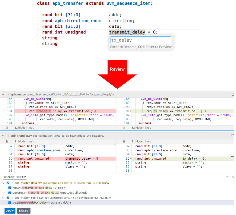
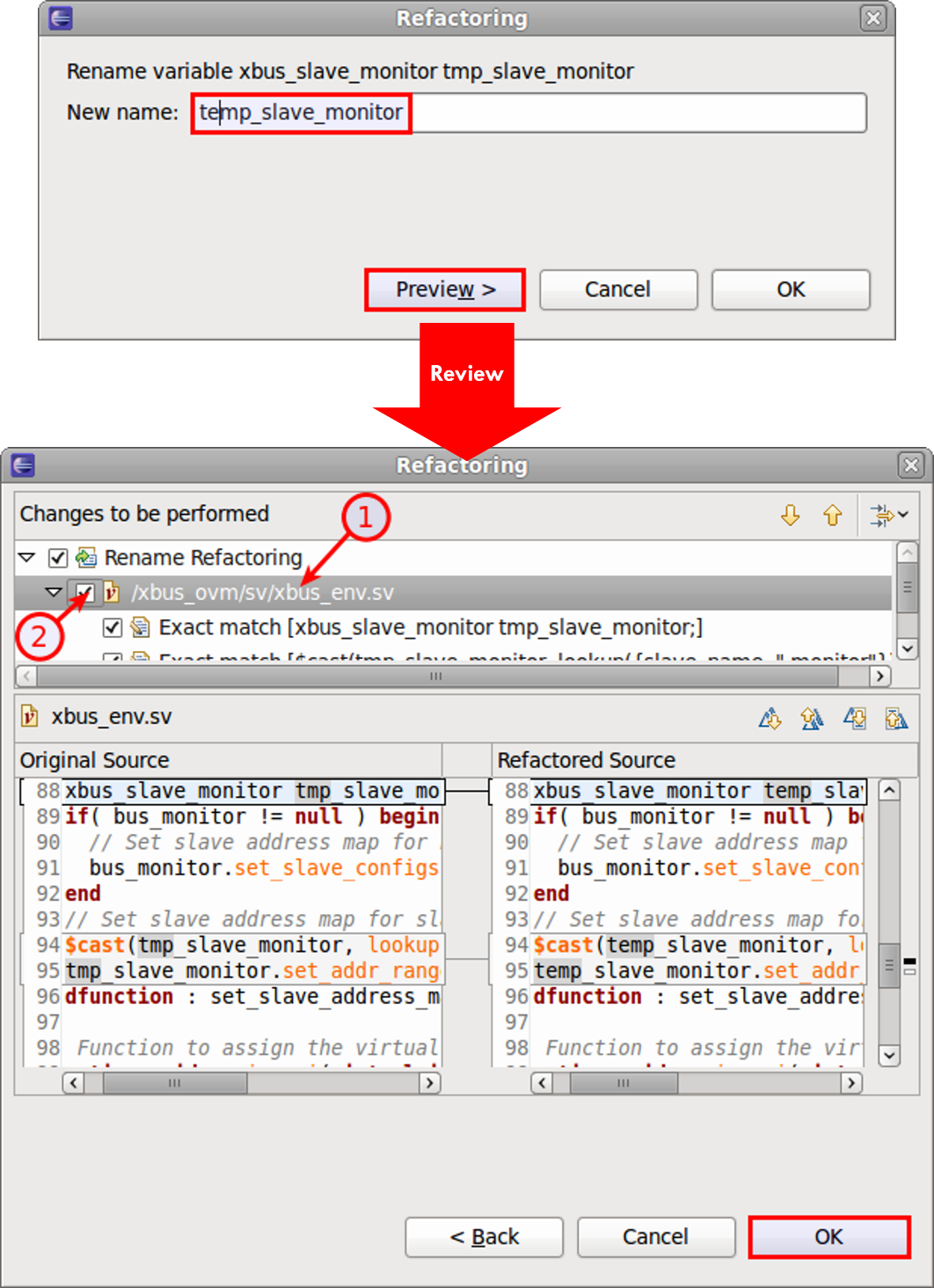
Refactoring Signal Names and Hierarchical Connections
You select the element to be changed (in Figure 1, a variable) and type in the new name. The IDE lists all files subject to the name change, and you can preview the proposed edits. Once you approve, the IDE updates your files and automatically rebuilds its internal database.
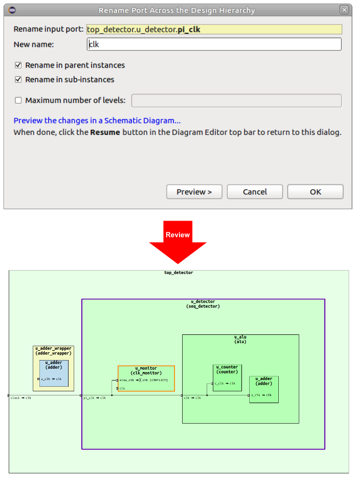
Propagating Port Renaming
One type of refactoring that is particularly hard to do by hand is uniformly renaming a port directly propagated across several levels of the design. As shown in Figure 2, the IDE provides an automated rename across the design hierarchy.
If the port is directly connected to a sub-instance port, then the sub-instance port is also renamed, and so on recursively across the whole sub-design hierarchy tree. If the port is directly connected to a parent instance port, then the parent instance port is renamed, and so on recursively up the design top.
For every port, both the definition and all its references are renamed. You have control over the new port name, renaming up/down/both directions, and the maximum number of hierarchy levels. You can preview changes in schematic diagrams.
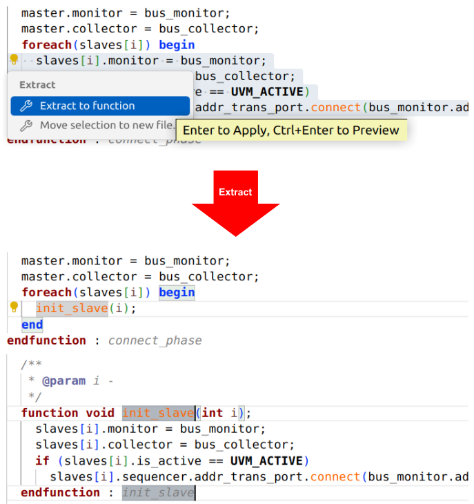
Extracting Code into Reusable Constructs
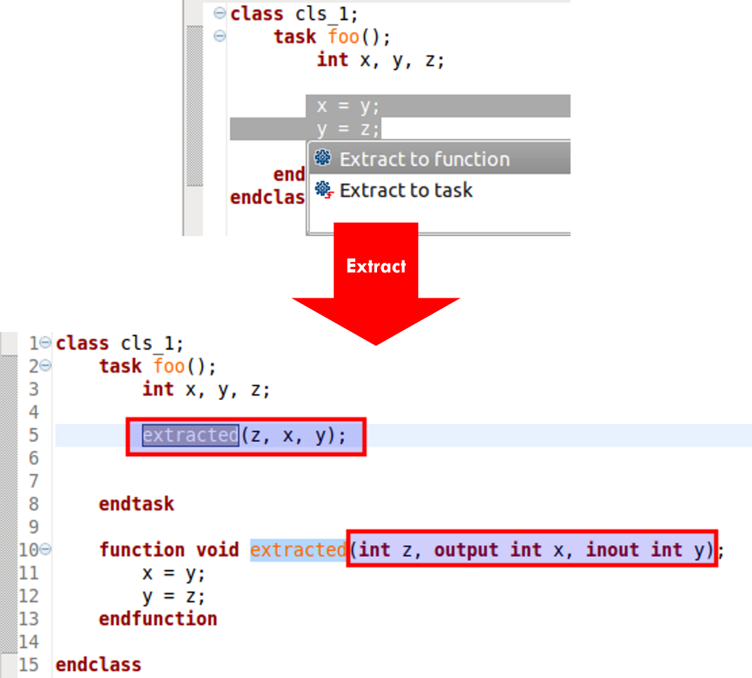
The IDE also supports extracting code to a function, task, module, method, or variable. Figure 3 shows how you can select the code to be extracted and specify the new function name. The IDE creates the function, adds its definition to the code, and replaces the extracted code with a call to the new function. You can even move a section of code to a separate new file simply by selecting the code and specifying the file name.
Switching Between Code Styles and Structures
There are many cases in which you’d like to combine or split sections of code, sometimes to take advantage of SystemVerilog’s many options for flexibility. For example, you can implement a class method within the class itself or prototype it with an out-of-block implementation. The IDE can automatically reorganize the code to convert back and forth between these two options. Figure 4 shows an internal implementation split out as external and an external method implementation folded into the class. You might need to change from one to the other to make a particular verification element conform to project coding guidelines.
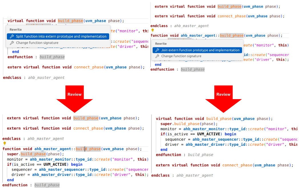
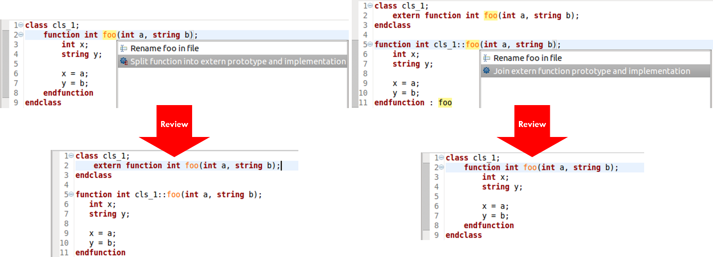
Figure 4 shows an example of a refactoring operation that you could do manually, although with some effort and risk of error. The IDE allows you to perform complex refactoring that would be even more challenging by hand.
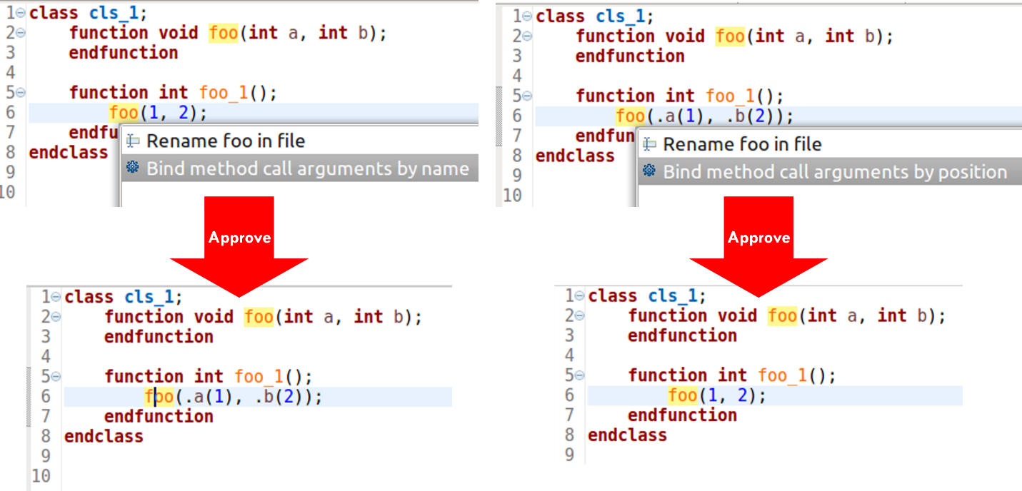
For example, Verilog and SystemVerilog let you specify module instance port connections and function call arguments by position or by name. The positional syntax is more concise, but can be confusing without explicit connections. The named syntax improves readability and it is not sensitive to argument or ports order, but it requires more typing. You might prefer to pick one style and stick with it, but conformance to your project coding guidelines may require conversion. Figure 5 shows the IDE automatically converting between the two styles.
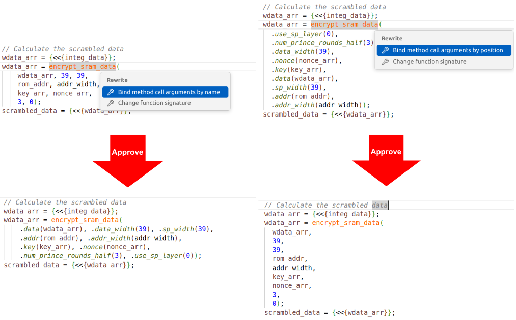
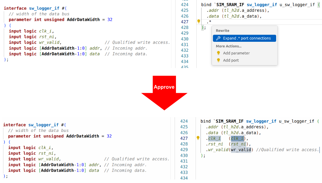
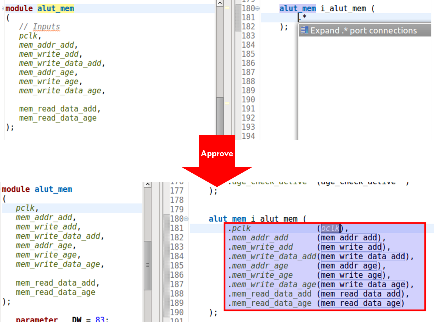
Being able to switch to named arguments with one click is very useful when reviewing or debugging code, since the connections are visible and you can easily see errors by inspection. A similar refactoring involves the SystemVerilog .* construct, which implicitly connects all ports to identically named signals. It’s very compact, but sometimes you might want to convert to a unified project coding style. Figure 6 shows the IDE performing this refactoring.
Expanding and Contracting Macros
Figure 6 is a good example of a refactoring operation you probably wouldn’t try by hand. Another example, also involving a type of expansion, involves macros.
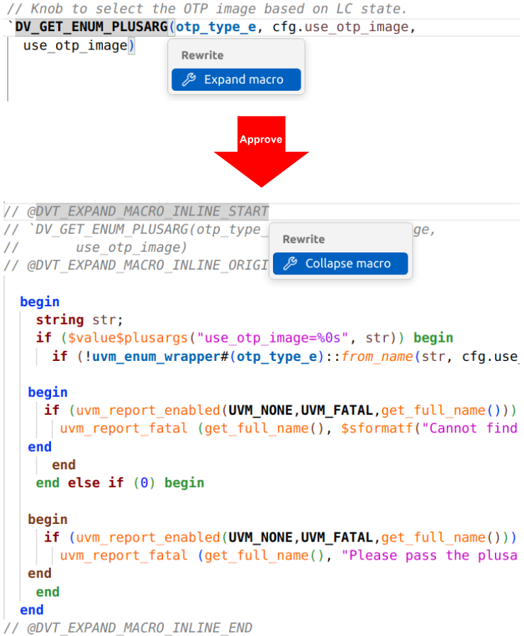
By far the biggest complaint about UVM is its reliance on macros. They make code much more concise and readable, but they also hide a lot of information. Expanding macros can be extremely valuable, especially during debug. As shown in Figure 7, the IDE supports both expanding and contracting macros automatically.
Safely Modifying Interfaces and Parameters
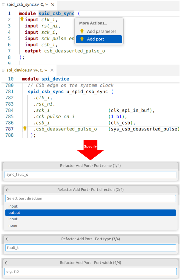
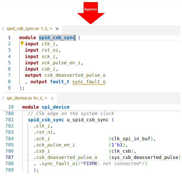
Another example demonstrates the ability of the IDE to safely reorganize parts of the design to aid in the refactoring process. You can easily add new ports to an existing module (Figure 8), with control over port name, direction, and width. The IDE adds the port to the module definition and adds an empty port connection to all instances of the module, along with a // FIXME comment to remind you to connect the new port.
Similarly, you can use the IDE to add a new parameter to a module, add or remove an argument to a method, or change the position of a method argument.
Refactoring Across Files Using Scripts
The interactive nature of the IDE makes it easy for you to experiment with different refactoring operations, preview proposed changes, and decide which operations to apply. Once you approve, the IDE updates your code and instantly rebuilds its internal model.
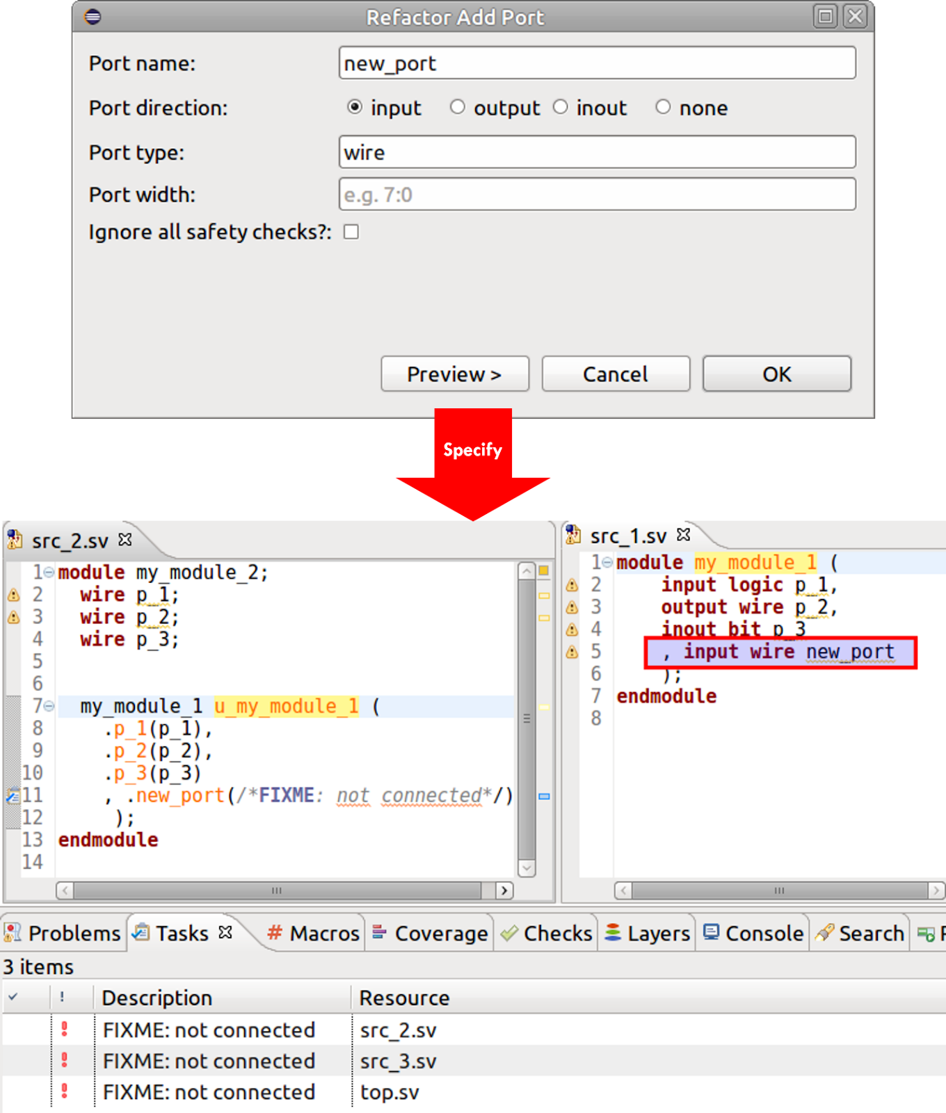
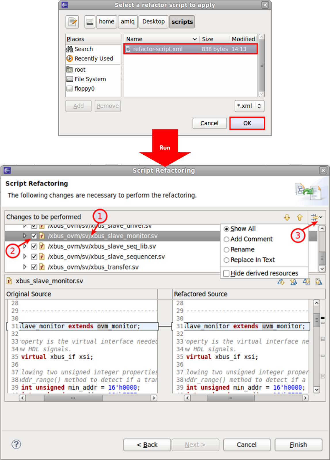
The IDE also supports refactoring scripts, which are XML files iterating changes to be performed on source code, scripts, or file/directory names. This automated process can run repeated operations on multiple files or at multiple times. Figure 9 shows selecting and running an XML script file. You can apply the changes immediately or inspect them one by one to be applied or skipped (bubbles 1 and 2). You can also filter the changes by refactoring type (bubble 3).
Conclusion
Refactoring, long established in the software domain, is now mandatory in the chip design and verification process. Refactoring can yield faster simulation, better synthesis PPA results, and more readable, reusable, and maintainable code. When performed manually, the amount of engineering effort involved must be traded off against these benefits. Automated, systematic refactoring with a tool like the DVT IDE family from AMIQ EDA changes the math completely.
Refactoring now takes little or no effort from you, and you can easily try out different operations to measure the results. With both DVT Eclipse IDE and DVT IDE for VS Code available, you have your choice of platform. You’ll be hooked as soon as you try the hardware IDE. See for yourself–get in touch with one of our support engineers to better understand how DVT IDE’s refactoring capabilities can help improve your code and much much more.