Introduction
Most, if not all, system-on-chip (SoC) designs today must meet strict requirements for low-power operation. This has led to many techniques to reduce power consumption, with major implications for both the design and verification teams. In the last few years, the concept of a power intent file that captures the key features has gained traction. Writing and maintaining this file is much easier with an integrated development environment (IDE) that supports power intent specification and can correlate it to the RTL for the chip design.
Low-Power Drivers
The most obvious reason for the elevated importance of power is that so many ubiquitous consumer devices run on batteries. From smartphones and wearables to tablets and laptops, many devices spend the bulk of their lifetime running on battery power. Although there have been some impressive advances in battery technology, the consumer always wants batteries to last longer. Even for large systems such as servers and network switches, “green” laws and the desire to manage electricity costs may require a lower-power design.
Fortunately, design engineers have come up with a wide range of techniques to reduce power consumption, from circuit-level innovations to system-level software control. Many of the techniques rely on dividing the chip design into power domains, each of which can be controlled independently. It may be possible to turn a power domain off and on entirely, a process that may require saving and restoring of essential state. In other cases, power may be reduced by lowering the voltage or the clock speed of the power domain. The popular dynamic voltage and frequency scaling (DVFS) technique does both.
In all cases, the idea is to minimize power for portions of the chip not currently critical for operation, with the ability to spin back up to full power and performance when needed. Some SoCs contain so much diverse functionality that there is never a time when the entire chip is active. Designers count on this, with the result that the chip would be destroyed by thermal runaway if all blocks were running. Proper specification and management of power domains are critical to prevent such a catastrophe.
As these techniques were invented and deployed, it turned out that significant portions of the low-power design and verification flow could be automated. For example, a tool with knowledge of the power domains could insert into the design isolation cells between blocks turned off and those still active, or level shifters between blocks running at different voltage thresholds. Such tools require some sort of input file defining power domains, power-control signals, and other relevant information.
Power Intent Specification
Recognizing the need for a standard format to specify power intent, the industry spawned two working groups. The Silicon Integration Initiative (Si2) defined Common Power Format (CPF) and Accellera defined Unified Power Format (UPF), now standardized IEEE Std. 1801-2015. Though they differ in some details, all power intent formats are intended to clearly document aspects of low-power design and to provide the information necessary for automated tools in the design and verification process.
An IEEE Std. 1801 or CPF specification is a file distinct from the RTL design description. This is deliberate in order to separate the intent from the implementation and potentially allow a single power intent file to be used with multiple variations of the design. However, this means that it is very easy for the two descriptions to get out of synchronization as the design evolves. Module and signal renames as well as changes in the design hierarchy can render the power intent file outdated and cause verification errors.
Defining power intent with its own unique, purpose-defined format makes it independent of the particular design and verification languages in use. Again, this offers the opportunity to reuse a file, or at least a good portion of it, across multiple projects. The downside is adding yet one more entry to the long list of languages and formats for SoC development teams to learn. Perhaps for this reason, adoption of UPF has been slower than expected in some companies and industry segments.
IDE to the Rescue
An integrated development environment (IDE) for SoC design and verification can provide a great deal of support for learning and using power intent specifications. Code can be analyzed in context, reflecting the structure of the specific languages and formats being used. A compiler runs behind the scenes all the time, processing the source code every time the engineers make a change and building an internal database of the design and the complete verification environment. A typical IDE can accomplish a wide range of very useful tasks, including:
- Performing syntactic checks on the code
- Performing static analysis checks on the code
- Highlighting and formatting the code
- Compiling or interpreting the code
- Linking to a simulator for debug
IDEs work equally well for any combination of programming languages, HDLs, dedicated verification languages such as e, the verification-related features of SystemVerilog, and power intent formats. With this knowledge compiled and available, the IDE can perform a much broader range of analysis and even offer suggestions to the designers and verification engineers as they enter or debug their code.
Intuitive Visualization
Perhaps the most obvious help that the IDE can provide in writing and verifying any sort of design or verification code, including a power intent file, is visualization. The IDE offers several views, including source code editor, hierarchy browser, and schematic. It is easy to navigate among these screens while following a signal or an element in the hierarchy. Color coding is frequently used as a way to visually link common elements across multiple views.
Figure 1 shows an example specifically relevant to low-power design. The IDE has read in the power intent specification as well as the other design and verification files and has determined the power domains. Each domain has a unique color that is shown in both the hierarchy browser and schematic views. This screenshot and the others that appear in the following examples are from the Design and Verification Tools (DVT) Eclipse IDE from AMIQ EDA.
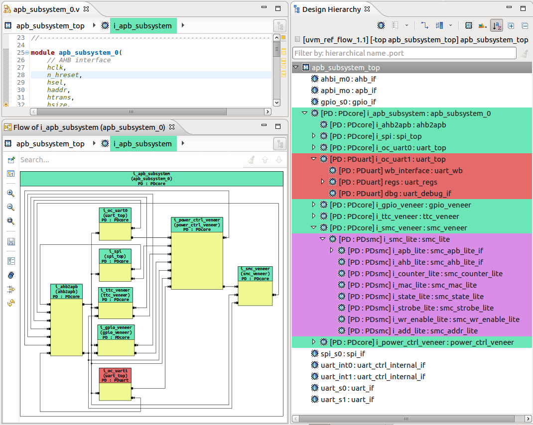
In this example, most of the design is in the “PDcore” power domain, which is shown in green. The UART block can be turned off independently if not needed; the “PDuart” domain is colored red. A third domain (“PDsmc”) is purple in the browser, but at a level of hierarchy not currently displayed in the schematic view. Expanding down into the SMC block would show the lower-level blocks in the PDsmc domain in purple as expected.
Interactive Development
The IDE is more than just a visualization platform; it is a development environment that proactively assists engineers with code entry. Because the IDE supports both UPF (IEEE Std. 1801-2015) and CPF (version 2.0), it has a complete definition of allowed syntax. If an engineer makes a mistake in a specification, for example typing “create_power_domains” into the UPF editor, the IDE will immediately report this as an error and will recommend a correction to the proper “create_power_domain” command.
The IDE also makes suggestions; typing in only “create_” will pop up a menu showing the possible auto-completions and allowing the user to choose one. As mentioned earlier, one of the complaints against UPF is that it is a new format to learn. By leveraging its built-in knowledge of language and specification standards, the IDE can greatly reduce the burden of up-front format memorization and thereby accelerate the learning process.
The IDE can also generate a template for the new command, showing which fields the user must fill in. For each field, as the user types a module or signal name from the design, both auto-completion options and error reporting are available. This greatly reduces the time it takes to create a power-intent specification, even for expert users who know the format well.
Consistency Checking
The difficulty in keeping multiple design and verification files in synchronization is a major challenge on SoC projects. Stand-alone specification files only exacerbate the problem. It is interesting to note that one of the reasons that SystemVerilog Assertions (SVA) is widely preferred over the Property Specification Language (PSL) standard is that assertions are included directly within the design and verification code. Using search-and-replace to change a variable name is likely to result in updates to assertions as well as to other references.
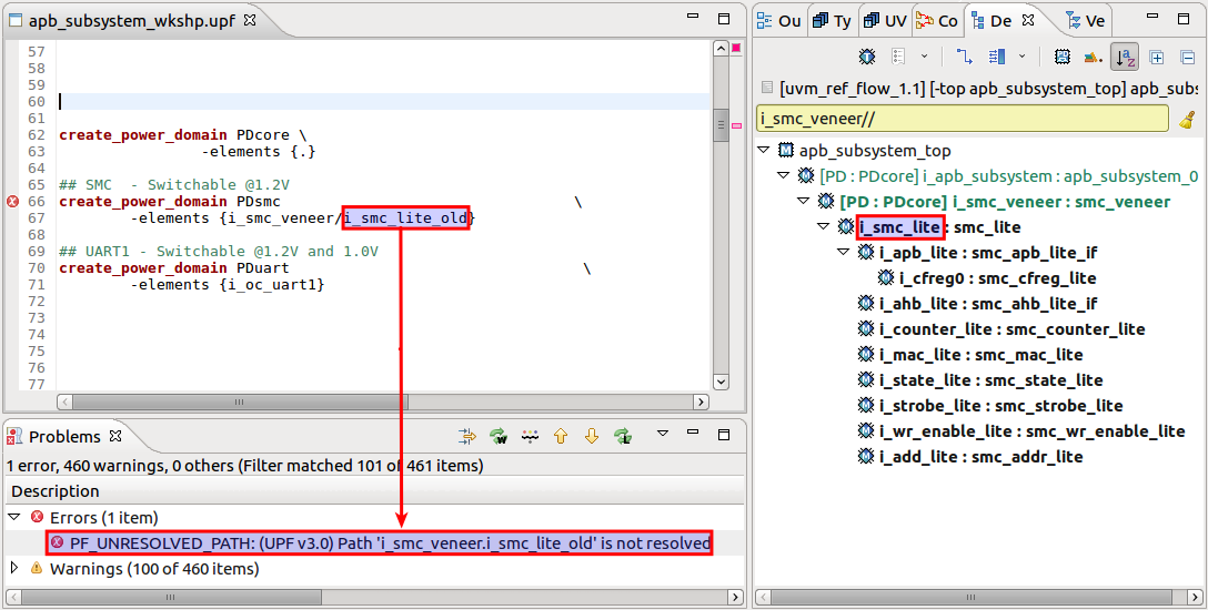
Although power intent specification is in a separate file, the IDE can bridge the gap between this file and others than might reference the same design names. Because it compiles on the fly whenever changes are made, it immediately cross-checks any edits to UPF/CPF or RTL files. Figure 2 shows an example of such a check. The RTL has been updated to change instance "i_smc_lite_old" to "i_smc_lite" but the UPF file still has the old name. The IDE instantly detects and reports this inconsistency.
Conclusion
Several factors are driving low-power design considerations for contemporary SoCs. Multiple techniques are available to reduce and manage power consumption, but the ability to control individual power domains offers a great deal of flexibility for hardware and software management. A clear, unambiguous definition of these domains and other aspects of power intent is required, using one of the specification standards available. By expanding to include support for power intent formats, the same IDE used to develop the design and verification code can ensure consistency across all files. The result is faster adoption, easier specification, and a more robust approach to low-power design.
This article was originally published by Elektronik.